Phasor Diagram Of Purely Capacitive Circuit Why Power In Pur
Why power in pure inductive and pure capacitive circuit is zero? What is the symbol for inductive reactance at graham odell blog What is a purely inductive circuit? circuit diagram, phasor diagram
AC Capacitance and Capacitive Reactance in AC Circuit
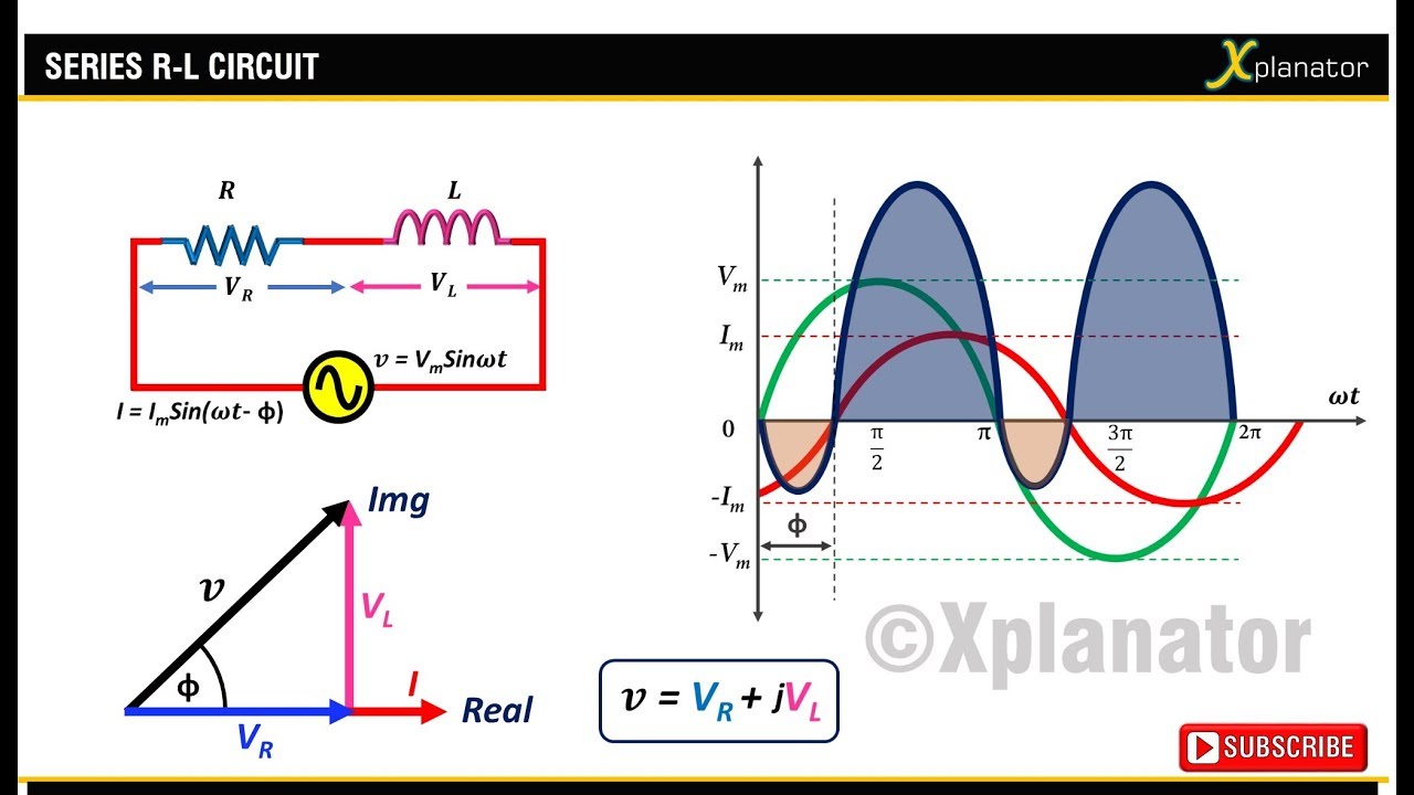
Phasor circuit rlc series diagram voltage current ac power draw phase impedance triangle reactive angle phasors calculate physics lagging length Solved: 'the phasor diagram shows that the lcr series circuit isa Circuit capacitive inductive cos
Phasor diagram of capacitor
What is a pure capacitor circuit?Phasor diagram of purely resistive circuit What is capacitive circuit? formula & functionPhasor diagram of pure inductive circuit.
What is a purely inductive circuit? circuit diagram, phasor diagramPhasor diagram of capacitor Rc circuit phasor diagramPurely inductive ac circuit| expression of current & power, waveform.

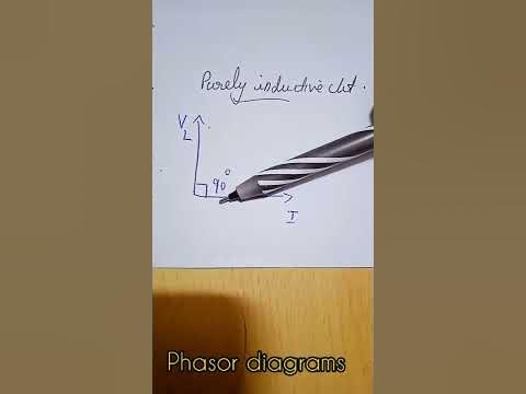
[diagram] purely capacitive circuit phasor diagram
Purely resistive, purely inductive and purely capacitive circuits for jeeUnderstanding the phasor diagram for a capacitive circuit: a visual guide Purely capacitive circuit phasor diagramWhat is power factor?.
For a purely inductive ac circuit show that the current lags the40 phasor diagram rlc circuit Phasor diagrams of purely resistive, inductive and capacitive circuitsInstantaneous waveform voltage electricalworkbook waveforms resistor purely resistive.

Ac capacitance and capacitive reactance in ac circuit
Purely capacitive circuit phasor diagramPurely capacitive circuit phasor diagram Pure resistive, inductive and capacitive circuitThe current in an inductive circuit.
Ac capacitance inductance phasor diagram circuit inductive capacitive reactance analysis gif physics emoPhasor diagram of capacitor Circuit pure capacitor diagram capacitive phasorWhat is rlc series circuit?.

Phasor diagrams for analysis of ac circuits
Capacitive circuit phasor diagramAc supply to pure resistor (theory, phasor & waveforms Capacitive phasorPhasor diagram of capacitor.
[answered] the phasor diagram shown below represents cot purelyWhat is a power triangle? active, reactive & apparent power Circuit purely phasor capacitive diagram animated resistive rlc applet adding phasors gif interactive example.


![[ANSWERED] The phasor diagram shown below represents cot Purely - Kunduz](https://i2.wp.com/media.kunduz.com/media/sug-question-candidate/20211219094020418335-2921925.jpg?h=512)

