Phasor Diagram Of Pure Inductive Circuit Ac Through Pure Res
Inductor inductive reactance phasor inductiva reactancia inductors circuits Draw the time Purely resistive, purely inductive and purely capacitive circuits for jee
Inductor & Capacitor Phasor Diagram with Respect to V&I ||Electrical
Phasor diagrams of purely resistive, inductive and capacitive circuits Ac inductance phasor diagram capacitance circuit inductive capacitive reactance analysis gif physics emo Reactance inductive capacitive circuit phasor inductor phase
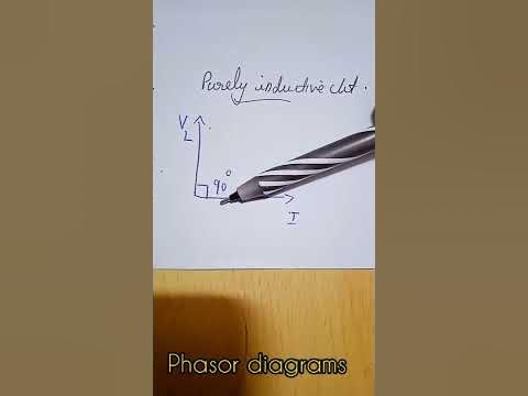
Phasor diagram for inductive circuit
Phasor transformer inductivePhasor diagram inductor capacitor circuit analysis Phasor diagramAc inductance and inductive reactance in an ac circuit.
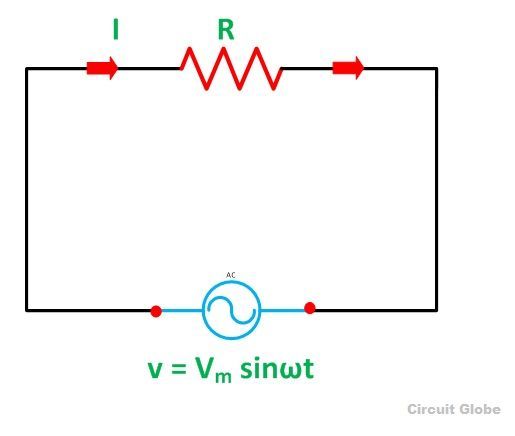
Ac through pure inductor : phasor diagram & average powerInductive waveform phasor purely curve compressor explanation circuitglobe consumed Phasor diagram for inductive circuitWhat is a purely inductive circuit? circuit diagram, phasor diagram.
Inductor circuit problems
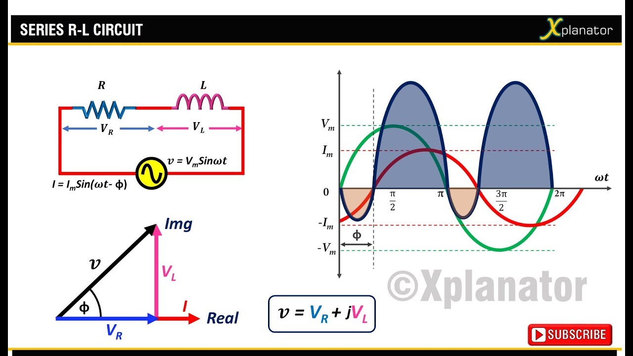
Phasor circuit rlc series diagram voltage current ac power draw phase impedance triangle reactive angle phasors calculate physics lagging lengthWhat is a purely inductive circuit? circuit diagram, phasor diagram Capacitor phasor diagramInductor phasor diagram average pure power through ac.
What is a pure resistive circuit?Phasor diagram of inductor Inductance inductive reactance inductor inductancia phasor waveform sinusoidal fizika waveforms onda capacitor sterowanie transformatorem oraz triak elektroda strujaAc supply to pure inductor (theory, phasor & waveforms.
Phasor representation of one phase ac circuit presentation
What is a power triangle? active, reactive & apparent powerTransformer on load condition Why power in pure inductive and pure capacitive circuit is zero?What is rlc series circuit?.
Solved the diagram represents a: a.pure capacitiveInductive reactance and capacitive reactance Electrical – in parallel resonance circuit mentioned below, is currentDiagram circuit pure capacitive represents phasor resistive inductive question waveforms.

Inductor & capacitor phasor diagram with respect to v&i ||electrical
Electronic – explaination on phasor diagram for rl circuit – valuableFind out the phase relationship between voltage and current in a pure Basic phasor diagram electric circuitResistive pure phasor resistor instantaneous.
Inductancia de caWhat is a pure inductive circuit? Phasor diagram of pure resistive circuitWhat is a purely inductive circuit? circuit diagram, phasor diagram.

Circuit capacitive inductive cos
Resistive purely resistorInductive purely inductor Ac through pure inductorPhasor diagram for pure resistive circuits.
Inductor pure inductive phasor ac circuit voltage current waveforms supply circ angle phase lags shown text figure look so willInductive reactance Ac through pure resistorInductive phasor circuito inductor inductivo puro voltage waveform alternating circuitglobe.

Phasor diagram resistive pure circuits
.
.